LCD Contrast Adjustment and Temperature Compensation
Contrast, or more appropriately put, the contrast ratio of a liquid crystal
display is the ratio of the light area of a display to the dark area. When
an LCD is used in a product, an allowance must be made to adjust the LCD
bias voltage. This adjustment will control the contrast between the
LCD segment being on and off, and this voltage needs to be optimized for the
best appearance. This adjustment needs to be made in production for
most LCD designs, and it may also need to be adjusted dynamically during
your products usage since temperature extremes may effect the LCDs contrast.
This section covers information on LCD contrast adjustment required to make
the display viewable, and also how to compensate for the correct contrast
over the full temperature range of your product.
![]() LCD CONTRAST
ADJUSTMENT
LCD CONTRAST
ADJUSTMENT
The LCD bias voltage that effects the LCD contrast, also effects the bias
angle of the display (see LCD Viewing Angles).
So at what angle you view the display will influence the setting of the LCD
bias voltage. Adjusting the contrast voltage, V , will effect the bias
angle to some extent, but not the viewing angle. A 12:00 display can be
optimized for a 6:00 viewing position by adjusting the contrast voltage. A
12:00 display set for 6:00 viewing position will not have as great a
contrast as a 6:00 display set for 6:00 viewing
position, and vice versa. Designers often want a display to be optimized for
straight-on viewing. Either a 12:00 or a 6:00 module can be used; and the
contrast voltage can be adjusted slightly to optimize the display for that
viewing position. Once the viewing position has been established for a
design, the contrast setting can be determined. This is normally done during
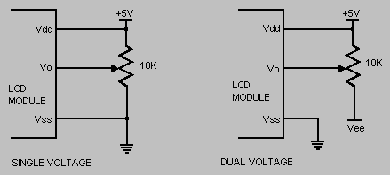
product development on the prototype unit. A potentiometer is connected
between the appropriate power supply rails (Vdd and Vss for single supply,
and Vee and Vdd for higher voltage LCD modules). The wiper of
the pot is connected to Vo (LCD bias voltage input, see below). The
LCD is then positioned at the nominal viewing position, and the pot is
adjusted to obtain the desired LCD appearance. Depending on the optimum
contrast requirement, and the ability to use more than one vendors LCD
module, you can either leave the potentiometer in the design, or measure the
voltage on the Vo pin and select a pair of resistors to produce this voltage
in the production units.

![]() LCD CONTRAST
ADJUSTMENT WITH TEMP COMPENSATION
LCD CONTRAST
ADJUSTMENT WITH TEMP COMPENSATION
Due to the contrast versus voltage versus temperature characteristics of
liquid crystal fluids, and the sensitive nature of display drive voltage
during multiplex operation, it may become necessary to compensate the LCD
drive voltage for applications where the display is subjected to wide
temperature excursions. For a typical Liquid Crystal fluid, with a negative
temperature coefficient, an under voltage condition with diminished display
contrast will result at low temperatures, and a "ghosting" or overdrive
condition will occur at high temperatures, if no compensation techniques are
employed. So if your application requires good contrast over a large
temperature range, you may need to consider temperature compensation for
your contrast adjustment circuitry.
When using an LCD module, one solution is to order an automatic temperature
compensation option (-TC option, if available) when you buy Pacific Display
Devices LCD modules. However, if you are using one of our modules
without this option, or if you are using one of our glass products, you need
to make your own temperature compensation circuitry. Listed below are
two possible temperature compensation circuits for your reference:
EXAMPLE 1
The first thing that needs to be determined in a particular application is
the typical LCD bias voltage (Vo) and the temperature coefficient of the LCD
module (Help in determining this is available at
techsupport@pacificdisplay.com).
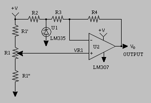
The figure below shows the basic temperature regulation circuit. The heart
of the circuit is U1, a National Semiconductor LM335 monolithic temperature
sensor, which should be placed in close proximity to the LCD. The LC335 has
a basic output voltage coefficient of 110mV/C. Resistor R2 supplies
operating current to U1, 1mA nominal. Difference amplifier U2 inverts and
scales this coefficient consistent with LCD driver requirements.
Potentiometer R1 provides a means by which the display operating voltage can
be set.

EXAMPLE 2
This example is more simplistic and is directed toward LCD module
applications. As with the first example, you need to determine the typical
LCD bias voltage (Vo) and the temperature coefficient of the LCD module
(Help in determining this is available at
techsupport@pacificdisplay.com).
Based on the temperature coefficient requirements, a thermistor (Rth + R3)
need to be selected to provide the correct offset for the temperature
coefficient generated by the LCD module. Resistor R1 will provide the
adjustment to select the correct initial voltage (or 2 fixed voltage divider
resistors) and transistor Q1 will provide the current buffer to allow the
Thermistor to operate with minimum loading. R2 is just used as a
minimum bias resistor for open circuit conditions. Vee must be a regulated
voltage source.