Multiplex Drive and Bias of LCD Technology
![]() LCD MULTIPLEX RATIO
LCD MULTIPLEX RATIO
The configuration for Liquid Crystal Display Multiplex Drive technique differs from a Static
Drive technique is that it uses more than a single "backplane" or segment
common. With this configuration, each segment control line can be connected
to as many segments as there are backplanes, providing that each of the
segments that it is connected to are tied to a separate backplanes.
This method "Multiplexes" each of the segment control lines and minimizes
the number of interconnects. This is the method used with complex
displays that have limited interconnection surface area or available drive
circuits. This reduction in the number of external connections
enhances device reliability and increases the potential display density. The
liability of a higher multiplex rate will effect display quality,
operational temperature range, and the increased complexity of drive
circuitry (or perhaps microprocessor software) may necessary for their
operation.
The method of drive for multiplexed displays is essentially a time division
multiplex with the number of time divisions equal to twice the number of
common planes used in a given format. As is the case with conventional LCDs,
in order to prevent irreversible electrochemical action from destroying the
display, the voltage at all segment locations must be caused to reverse
polarity periodically so that zero net DC voltage is applied. This is the
reason for the doubling in time divisions: Each common plane must be
alternately driven with a voltage pulse of opposite polarity.
As is the case with non multiplexed displays, the drive frequency should be
chosen to be above the flicker-fusion rate, i.e. >30 Hz. Since increasing
the drive frequency significantly above this value increases current demand
by the CMOS drive electronics, and to prevent problems due to the finite
conductivity of the display segment and common electrodes, an upper drive
frequency limit of 60-90 Hz is recommended.
![]() LCD BIAS
LCD BIAS
The control signals that drive an LCD are AC in nature. The basic configuration of how to generate a waveform to control an LCD are covered in the sections "LCD Multiplex Ratio (above)" and "LCD Static Drive Technology". But to control LCDs with a larger multiplex ratio, we need to provide the waveform generator with multiple bias voltage level points. The resulting waveform sent to the LCD segment/dot control lines and backplane commons will contain a stair-stepped waveform that will maintain specific ac voltages across any given segment/dot to keep it in it's "on" or "off" state (or in a grayscale module, states between those two points). The LCD Bias number (example: 1/5 bias) will indicate how many voltage reference points are created to drive a specific LCD. The table below shows the relationship between the number of driving bias voltages and the display multiplex ratios typically used:
| Mux Ratio |
Static | 1/2 | 1/3 | 1/4 | 1/7 | 1/8 | 1/11 | 1/12 | 1/14 | 1/16 | 1/24 | 1/32 | 1/64 |
| Biases | 2 | 3 1/2 Bias |
4 1/3 Bias |
5 1/4 Bias |
6 1/5 Bias |
||||||||
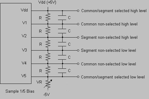
The necessary bias voltages are usually generated by the use of a resistor
dividing network, and example of which is shown below using Vdd
at 5 volts, and the number of resistors in the ladder determined
using the table above.
The values of the resistors is determined by the required voltage reference
points and possible
waveform distortion. Because an LCD is a capacitive load, the values should
be decreased to decrease distortion, or with larger displays, buffering the
voltage reference points with op-amps.